Differential pressure (DP) transmitters are the workhorses of industrial level measurement. You can find them on vessels holding everything from harsh chemicals to ultrapure water, silently converting a simple pressure reading into a precise level value. The core idea is elegantly simple: the weight of a liquid column creates pressure, and if you measure that pressure, you know the height. Yet the real-world details—density shifts, wet leg offsets, and calibration traps—trip up even seasoned technicians. This article explains exactly how differential pressure transmitters measure level, from the physics to the installation fine points, so you can apply the method reliably in your own plant. Whether you manage a hydrogen storage system, a lithium battery slurry tank, or a municipal water network, the principles hold.
Key Takeaways
– DP level measurement relies on hydrostatic pressure: a 27.7-inch water column exerts 1 psi, giving a linear, calculable relationship. – A DP transmitter’s high side senses the liquid head; the low side either vents to atmosphere or compensates for vessel pressure, enabling accurate level inference. – Correct installation, impulse line filling, and zero trimming eliminate hidden errors that cause 5–15% reading drift in many field installations. – Liquid density variations must be handled with either manual SG inputs or dynamic compensation, avoiding level errors over 10% in multi-product tanks. – When paired with modern digital instrumentation, DP level loops deliver repeatabilities of ±0.1% of span and turndowns exceeding 100:1.
What Is a Differential Pressure Transmitter for Level Measurement?
A Differential Pressure (DP) Transmitter measures the pressure difference between two points and converts the signal into a level measurement value.
For tank level applications:
● High-pressure side → Connected to the bottom of the tank
● Low-pressure side → Connected to the top of the tank or atmospheric reference
The pressure difference generated by the liquid column is proportional to the liquid height and density.
How Does a Differential Pressure Transmitter Measure Level?
Open Tank Level Measurement
For open tanks, the high-pressure side connects to the bottom of the tank, while the low-pressure side is exposed to atmospheric pressure.
The transmitter measures the hydrostatic pressure created by the liquid column.
Applications:
● Water tanks
● Storage tanks
● Open process vessels
Closed Tank Level Measurement
For sealed or pressurized tanks, the pressure above the liquid can affect measurement accuracy.
The low-pressure side connects to the vapor space to compensate for vessel pressure, allowing the transmitter to measure only the liquid head pressure.
Applications:
● Chemical reactors
● Pressure vessels
● Steam systems
What You Need Before Starting
Before diving into configuration steps, assemble a clear picture of your process and the right hardware. Overlooking these prerequisites leads to rework and unreliable data.
– Process fluid data: know the specific gravity (SG) at operating temperature, because a 0.01 SG shift changes level calculation by 1 inch per 100 inches of water column. If your fluid density varies—common in hydrocarbon blends or pulp slurries—plan for an external density reference or a multivariable transmitter. – Vessel design details: open or closed tank? Is there a blanket gas? A closed tank with a non-condensing vapor requires a dry leg; a condensing vapor needs a wet leg filled with a reference liquid like glycol or glycerin. – Transmitter specification: a DP transmitter with a rated accuracy of 0.075% of span and a maximum working pressure (MWP) above your vessel’s MAWP, typically 300 to 2,500 psi depending on the model. For corrosive fluids, diaphragms with Hastelloy C-276 or tantalum wetted parts are common. – Companion instrumentation: while the DP transmitter handles level, you may need separate flow measurement on filling or discharge lines. Shanghai Lisen Measurement & Control Technology Co., Ltd., founded in 2004 and based in Shanghai, supplies a full range of devices for such tasks, including the Flowmeter series used across industries from natural gas to food processing.
Step 1 — Grasp the Hydrostatic Head Principle Before Touching Any Instrument
Every DP level measurement derives from one physical fact: the pressure at the bottom of a static liquid column is proportional to its height, density, and gravity. The math is straightforward. In US units, a 1-foot column of water (SG = 1.0) produces 0.433 psi. In SI units, a 1-meter column of water generates about 9.81 kPa. So for a tank holding a fluid of SG = 0.85, the pressure per foot is 0.433 × 0.85 = 0.368 psi. If your transmitter sees that 0.368 psi, you infer 1 foot of level. Scale that linearly over the full height.
Why This Matters
Misunderstanding the density factor causes the most common level blunder. A technician sets the transmitter’s span using water values, but the tank actually holds 98% sulfuric acid, SG = 1.84. The true level will be nearly half of what the transmitter reports, risking overfills. Write the formula P = h × ρ × g on your startup sheet and check the actual fluid density before dialing in any numbers.
Common Mistakes to Avoid
– Assuming water density: always confirm the liquid SG at process temperature. A water-based 30% caustic soda solution has an SG of about 1.33 at 20°C, far from 1.0. – Ignoring atmospheric pressure changes: an open-tank installation vents the low side to air. Barometric shifts of 0.1 psi (roughly 2.3 inches of water) drift the reading if the transmitter isn’t zeroed with the low side open.
Step 2 — Select the Right DP Transmitter and Pressure Taps
Not every DP transmitter suits level service. Look for models with robust overload protection: even a low-range unit must tolerate full line pressure on one side during commissioning. Common rangings for level run from 25 inches of water column (about 0.9 psi) for short vertical tanks up to 1,000 inches WC (about 36 psi) for tall distillation columns. For pressurized vessels, the static pressure line rating must exceed the maximum operating pressure. Many plants standardize on class 300 or class 600 flange ratings.
What to Do
1. Determine the maximum liquid height from the lower tap to the overflow or upper nozzle. Add 10–15% margin to define the upper range value. 2. Calculate the corresponding pressure in your preferred units: psi, kPa, or mbar. For a 12-foot-tall tank with SG = 0.9, the pressure at the low tap with a full vessel is 12 × 0.433 × 0.9 = 4.68 psi. Choose a transmitter with a span of 0–5 psi or 0–10 psi. 3. Select the diaphragm material and fill fluid. Silicone oil is standard for moderate temperatures (−40 to 200°C); for high-temperature services, use a high-temperature fill like DC 704. If the fluid is food-grade, tri-clamp sanitary seals and FDA-approved fill fluids are mandatory.
Why This Matters
A transmitter that runs near its full span delivers better signal-to-noise ratio. Picking a 0–50 psi device for a 4 psi application wastes resolution; the output will be only 8% of range, making a 0.1% error in the transmitter’s accuracy large relative to the reading.
Common Mistakes to Avoid
– Neglecting fill fluid vapor pressure in vacuum service: a vacuum can boil standard silicone oil, cause diaphragm damage, and shift zero by 20% or more. Always request a low-vapor-pressure fill for vacuum columns. – Forgetting that the high side impulse line needs process isolation: install a block valve and, for slurry services, a diaphragm seal with a flushing port to prevent solids plugging.
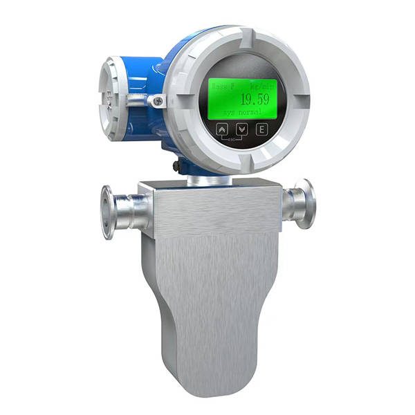
Where the process demands high-accuracy mass flow data alongside level—for instance, during reactor charging—many engineers add a Coriolis mass flowmeter to independently measure density and mass flow, feeding real-time density to the level loop.
Step 3 — Install the Transmitter and Impulse Lines Correctly
The physical layout makes or breaks measurement repeatability. Mount the transmitter below the lower tap whenever possible, so any condensate or liquid in the impulse lines remains in place as a stable reference leg. For a dry leg on a closed tank, slope the impulse tubing at least 1 inch per foot downward toward the vessel to let condensate drain back.
What to Do
1. Connect the high side to the vessel’s lower pressure tap, located at the 0% level point. If that tap is not at the absolute bottom, document the elevation offset. 2. For closed tanks, connect the low side to the upper tap, above the maximum liquid level. This subtracts the vapor space pressure. 3. Fill a wet leg completely with a known-diameter liquid (often the process fluid itself if non-freezing, or a glycol-water mix). Mark the exact fill SG—25% glycol in water has an SG around 1.03 at 20°C—and record the vertical height of the wet leg column. 4. After filling, bleed all air from both legs using the transmitter’s vent screws. A single 2 mm bubble in the high side creates a few inches WC error.
Why This Matters
Any trapped gas acts as a compressible spring, damping the pressure signal and causing hysteresis that can reach 0.5% of reading. In level applications where the span is only 40 inches of water, that’s a 0.2-inch error that refuses to calibrate out.
Common Mistakes to Avoid
– Venting the low side of an open tank to a closed pipe: the reference must be truly vented to atmosphere. A capped pipe traps pressure and shifts zero by up to 1 psi with temperature. – Poor wet leg maintenance: if the fill liquid evaporates or freezes, the static head offset drifts. Schedule seasonal wet leg refill inspections.
Step 4 — Configure Zero, Span, and Apply Elevation/Suppression
With the transmitter physically installed and purged, you apply the calculated pressures for zero and span. This step translates the pressure range into a 4–20 mA signal representing 0–100% level.
What to Do
1. With the vessel empty (or at the 0% level) and the wet leg filled, the transmitter sees a differential equal to (height of wet leg × SG_wetleg) minus zero liquid head. Suppose the wet leg is 5 feet tall and SG = 1.03, then the wet leg pressure is 5 × 0.433 × 1.03 = 2.23 psi. The vessel’s high side sees zero liquid pressure. The measured differential is −2.23 psi because the low side pressure exceeds the high side. Set this as the LRV (4 mA) via zero suppression. 2. Now calculate the full-level condition for a liquid of SG = 0.9, tank height 12 feet above the tap. Liquid hydrostatic pressure = 12 × 0.433 × 0.9 = 4.68 psi. The wet leg pressure remains 2.23 psi. The differential = 4.68 − 2.23 = 2.45 psi. Set URV (20 mA) to 2.45 psi. 3. Use a HART communicator or the local display to enter these values. Many transmitters allow direct entry of zero/suppression values in engineering units.
Why This Matters
Misapplied suppression is the second-largest error source after density. If you forget the negative sign, the transmitter will read 0% at some intermediate level and saturate at 4 mA when empty—looking like a dead transmitter.
Common Mistakes to Avoid
– Using dry-leg math for a wet-leg installation: the large negative bias must be programmed, not ignored. – Neglecting to trim the transmitter after installation: an airtight seal test and an applied pressure zero trim at operating temperature reduce drift below 0.05%.
Step 5 — Compensate for Density Variations and Process Dynamics
Real tanks rarely hold a liquid of constant density. Temperature swings of 50°C can change water density by 1–2%, and blending operations alter SG continuously. If you don’t compensate, a reading that is perfectly accurate at 20°C might be 3 inches off at 80°C on a 10-foot tank.
What to Do
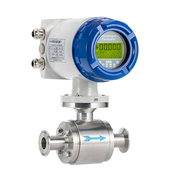
1. Measure the operating temperature at a representative point and apply a correction factor. For water, density drops from 998 kg/m³ at 20°C to 972 kg/m³ at 80°C—a 2.6% change. Multiply the transmitter’s output by (ρ_reference / ρ_actual) in your DCS or PLC. 2. For multi-fluid service, wire a density meter into the control system and multiply live. A Electromagnetic flowmeter can infer density when combined with a Coriolis meter or can at least provide an independent flow check, but in level compensation, a direct vibrating-element densitometer is more common. 3. If you cannot measure density, set conservative high and low level alarms based on the worst-case density extremes. During a water-hydrocarbon changeover, for example, allow 10% extra margin.
Why This Matters
Without density compensation, a tank full of a dense product will read as overfilled, while a switch to a light solvent will show low level. Operators lose confidence in the instrument and start guesstimating—exactly what an automated system should eliminate.
Common Mistakes When Using DP Transmitters for Level Measurement
Differential Pressure (DP) Transmitters are widely used for tank and vessel level measurement. However, incorrect selection, installation, or calibration can cause inaccurate readings and unstable operation.
Ignoring Liquid Density Changes
DP transmitters calculate level based on hydrostatic pressure, which is affected by liquid density.
Density changes caused by temperature, concentration, or different process media may lead to measurement errors. Proper calibration should be performed for applications with variable density.
Selecting the Wrong Pressure Range
An incorrect pressure range can reduce measurement accuracy or damage the transmitter.
Consider:
● Minimum and maximum liquid level
● Tank height
● Operating pressure
● Liquid density
Choose a suitable range to ensure stable and accurate measurement.
Incorrect Impulse Line Installation
Improper impulse line installation may cause measurement errors.
Common issues include:
● Air bubbles in liquid measurement lines
● Blockage from impurities
● Incorrect piping arrangement
Proper installation helps maintain reliable pressure transmission.
Choosing Unsuitable Diaphragm Materials
The diaphragm material must match the measured medium.
For corrosive or aggressive fluids, unsuitable materials may cause corrosion, leakage, or reduced service life. Select compatible materials such as Hastelloy or PTFE when required.
Incorrect Wet Leg or Dry Leg Configuration
Closed tanks require proper wet leg or dry leg configuration.
Incorrect setup may result in:
● Zero point errors
● Incorrect level readings
● Calibration difficulties
The configuration should be selected according to vessel pressure and process conditions.
Neglecting Calibration and Maintenance
Regular calibration and inspection are essential for reliable DP level measurement.
Recommended practices:
● Check zero and span settings
● Inspect connections and impulse lines
● Perform periodic calibration
Proper maintenance helps extend transmitter life and improve measurement accuracy.
Pro Tips for Success
– Calibrate with the actual process liquid whenever possible. Fill a sight glass or weigh cell to verify the level—one plant reduced startup time by 40% after switching from theoretical span to a wet calibration. – Install a three-valve manifold for online zero checks. Close the block valve, open the equalizer, and verify that output (LRV) remains stable to within 0.02%—a 5-minute check that prevents month-long drift. – Use the HART signal to pull secondary variables. Many transmitters report static pressure and sensor temperature, letting you detect plugged impulse lines or a failing wet leg before readings become erratic.
Frequently Asked Questions
Why does a DP transmitter need a wet leg in some closed tanks and not others?
A wet leg is required when the vapor above the liquid can condense in the low-side impulse line, causing unpredictable pressure changes. By filling the low side with a stable reference liquid, you lock in a constant head pressure that the transmitter can subtract as a fixed offset, returning accuracy to within 0.1% of span.
Can I use the same DP transmitter for level and density measurement?
Yes, if the tank height is constant and the level is kept fully submerged, the DP transmitter reads pure hydrostatic pressure proportional to density. Many biotech reactors use this dual role with a fixed head column, achieving density measurements accurate to ±0.001 g/cm³ when the transmitter has a 0.04% accuracy.
What causes a DP transmitter to drift over time even with a stable process?
Drift often stems from fill fluid migration in diaphragm seals, especially under vacuum or high temperature cycles. Annual verification against a precision pressure calibrator catches shifts early; typical drift limits are 0.125% of URL per year for a quality instrument.
How do I handle a tank that contains a pressurised gas blanket and the blanket pressure fluctuates?
The DP transmitter measures the difference between the bottom liquid pressure and the headspace pressure. As long as the low side is connected to the vapour space, the subtraction is automatic. Fluctuations of even 50 psi are cancelled, leaving only the liquid head signal.
Conclusion
Differential pressure transmitters measure level by converting the weight of a liquid column into a simple pressure reading—a principle as old as the industry but still unmatched for ruggedness and value. Once you understand the hydrostatic head, select a transmitter matched to your specific gravity and span, install it with proper dry or wet leg, and dial in zero suppression, the loop will deliver repeatable level data for years. The real skill lies in the details: accounting for density changes, maintaining fill fluids, and checking zero occasionally. Shanghai Lisen Measurement & Control Technology Co., Ltd. supports these applications with a complete instrument portfolio, from DP transmitters to the Flowmeter series, the Coriolis mass flowmeter for mass flow and density, and the Electromagnetic flowmeter for conductive liquid loops. With a service network across China and products proven in hydrogen, petrochemical, photovoltaic, and food sectors, we can help you bring the same reliable level measurement to your operation. Next step: pull the fluid data sheet, calculate your hydrostatic span, and give us a call to discuss the right configuration—start measuring, not guessing.