Electromagnetic Water Flow Meter Guide for Industrial Water Measurement
Introduction
Electromagnetic water flow meters have become the default choice for many industrial water measurement jobs because they have no moving parts, handle dirty water, and deliver repeatable volumetric readings. Yet a meter only performs well when it is specified, installed, and maintained correctly. This electromagnetic water flow meter guide for industrial water measurement walks engineers, maintenance planners, and utility buyers through a practical four-step process: confirming process data, selecting the right meter configuration, installing it for a full pipe, and commissioning it against field conditions.
Traditional mechanical and turbine meters struggle with suspended solids, scaling, or low-pressure drop requirements. An electromagnetic meter removes the mechanical obstruction and measures flow by Faraday’s law of electromagnetic induction. The catch is that the water must be sufficiently conductive and the meter must be grounded properly. Shanghai Lisen Measurement & Control Technology Co., Ltd., founded in 2004 in Shanghai, China, supplies a range of electromagnetic flow meters for water applications. This guide references ISO 20456 for electromagnetic flowmeter use and OIML R49 for water meter requirements where relevant.
Key Takeaways
- Confirm conductivity, flow range, pressure, temperature, and pipe size before choosing a meter.
- Match liner and electrode materials to water chemistry to avoid premature failure.
- Install with straight pipe runs and full-pipe conditions for stable ±0.2% to ±0.5% readings.
- Ground the meter correctly to stop electrical noise from corrupting the measurement.
- Verify zero and calibration points during commissioning and re-check annually or after process changes.
What You Need Before Starting
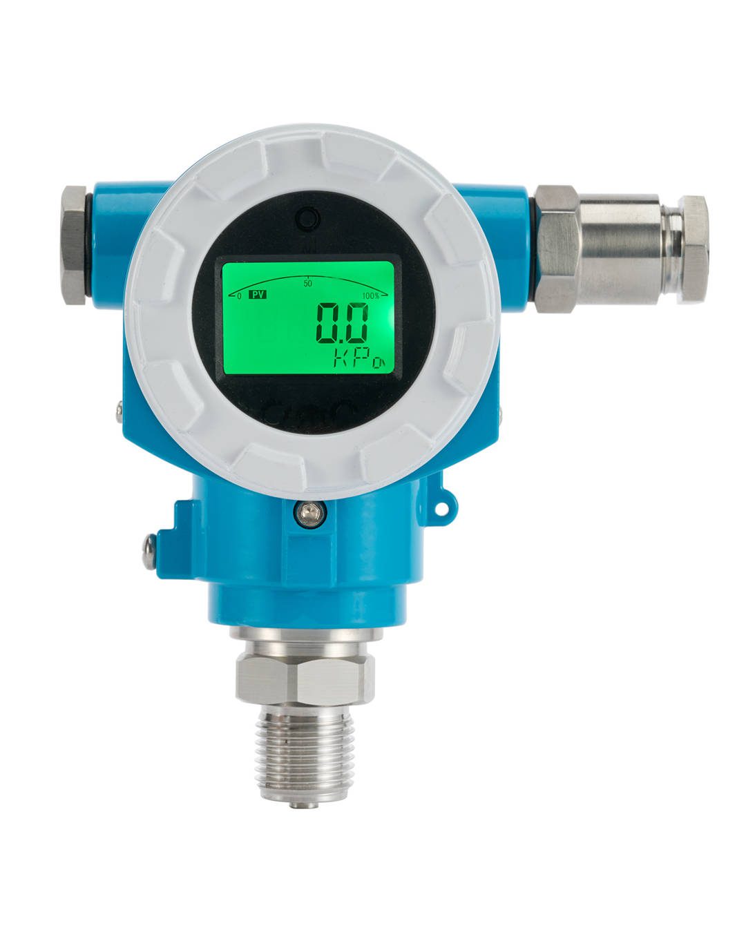
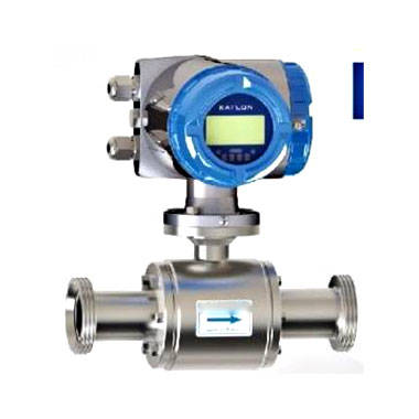
Before starting, collect the process data sheet, pipe layout, water quality report, and access to the Flowmeter series catalog to compare electromagnetic, ultrasonic, and mass options. You also need the Electromagnetic flowmeter product page to review available models such as MAG1000 Standard type, MAG2000 Wafer type, MAG3000 Sanitary type, MAG4000 Stainless steel type, MAG5000 High pressure type, and MAG8000 water meter type. If the application involves non-conductive liquids or mass-based billing, keep the Coriolis mass flowmeter as a comparison point. The essential inputs are:
- Minimum, normal, and maximum flow rate in m³/h or L/s
- Pipe inner diameter and process connection type
- Water conductivity, pH, chloride level, and temperature range
- Operating pressure, including any cleaning or CIP excursions
- Grounding access and local electrical noise conditions
Step 1 — Lock Down the Process Data Before Selecting a Model
What to Do
- Record minimum, normal, and maximum flow rates in the same units, usually m³/h or L/s.
- Measure or obtain the pipe inner diameter, not just the nominal pipe size.
- Confirm the water’s electrical conductivity. Electromagnetic meters normally need at least 5 µS/cm; potable and process water are usually far above that.
- Note operating pressure and temperature, including cleaning or CIP excursions.
- Identify the process connection preference: flanged, wafer, sanitary, or high-pressure.
Why This Matters
Electromagnetic flow meters work only with conductive liquids. If the fluid falls below the required conductivity threshold, the signal becomes unstable or disappears. Pressure and temperature drive liner selection: rubber liners typically handle moderate temperatures, while PTFE or PFA liners suit higher temperatures and aggressive water. Flow range affects meter size. The best accuracy is usually between 1 m/s and 5 m/s, with maximum recommended velocities around 10 m/s for continuous service, as stated in general ISO 20456 guidance. A meter sized too large runs below its usable range and loses accuracy.
Common Mistakes to Avoid
- Using pipe size as meter size: This often forces the meter to operate below 0.3 m/s. Size the meter by flow velocity, not by the existing pipe diameter alone.
- Ignoring temperature spikes: A liner that handles 60°C may fail during an 85°C CIP cycle. Verify both continuous and transient temperatures.
Step 2 — Match Liner, Electrode, and Connection Type to the Water
What to Do
- Review the water chemistry report for pH, chloride, solids, and chemical additives.
- Choose an electrode material. Stainless steel 316L works for most potable water and cooling water. Hastelloy C suits high-chloride or brackish water; titanium resists seawater and oxidizing media.
- Choose a liner material. Hard rubber suits clean water and wastewater. PTFE or PFA suits chemical exposure and higher temperatures. Ceramic is used for abrasive media.
- Select the process connection. The Electromagnetic flowmeter range includes MAG1000 Standard type, MAG2000 Wafer type, MAG3000 Sanitary type, MAG4000 Stainless steel type, MAG5000 High pressure type, and MAG8000 water meter type, so the connection and pressure class can be matched instead of forced.
- Decide on an integral or remote transmitter based on installation access and ambient temperature.
Why This Matters
Electrode and liner compatibility determines service life and measurement stability. A wrong electrode in chlorinated water can pit within months, producing noise and drift. Liner swelling or cracking can expose the magnetic coils to water and destroy the meter. Sanitary connections are required for food or pharmaceutical water because they avoid dead legs and allow CIP. High-pressure designs need reinforced flanges and pressure ratings; general industrial meters often use PN16 or PN40 flanges, but always verify class against the pipe specification.
| Component | Material | Common industrial water application |
|---|---|---|
| Electrode | 316L stainless steel | Potable water, cooling water, low-chloride process water |
| Electrode | Hastelloy C | High-chloride, brackish, or acidic water |
| Electrode | Titanium | Seawater, brine, and strongly oxidizing streams |
| Liner | Hard rubber | Clean water, wastewater, and slurries up to moderate temperature |
| Liner | PTFE / PFA | Chemical water, high temperature, aggressive cleaning agents |
| Liner | Ceramic | Abrasive slurries and high-velocity water |
Common Mistakes to Avoid
- Choosing the cheapest electrode for aggressive water: Check chloride and oxidizing potential before settling on stainless steel.
- Overlooking connection pressure class: A wafer meter designed for PN16 will fail if installed in a PN40 line without proper rating.
Step 3 — Install for a Full Pipe and Clean Ground
What to Do
- Position the sensor so the pipe remains full at all times. For horizontal lines, install the meter in a low point or uphill section, never in a free-draining section.
- Maintain the supplier’s required straight pipe run. Many electromagnetic meters need 5D upstream and 3D downstream for standard accuracy, but some advanced designs tolerate 0D to 3D upstream. Always follow the specific model’s installation manual.
- Bond the meter body, process pipeline, and grounding rings to a proper earth point. Some designs use built-in reference electrodes; others need grounding rings in lined or plastic pipes.
- Avoid air bubbles by locating the meter away from pump suction, air release valves, or cascading inlets.
- Mount the transmitter in a dry accessible location if it is remote; use IP65 or higher per IEC 60529 for washdown areas, and IP68 if the sensor may be submerged.
Why This Matters
An electromagnetic meter produces a microvolt-level signal that is easily polluted by electrical noise, stray currents, or air bubbles. A partially full pipe creates a false flow signal because the electrodes may not remain wetted. Incorrect grounding is a frequent source of unstable readings. ISO 20456 recommends full-pipe operation and proper electrical bonding to ensure the measured voltage represents the true mean flow velocity.
Common Mistakes to Avoid
- Mounting in a rising pipe after a bend without enough run: Swirl and asymmetric velocity profile lower accuracy.
- Grounding to the wrong point: Ground loops from nearby motors or VFDs can inject noise. Use a single, clean earth path per the manufacturer.
Step 4 — Commission, Verify, and Document the Setup
What to Do
- Turn on the meter and let it stabilize for at least 30 minutes before taking readings.
- Check the empty-pipe detection if available, and confirm the meter displays zero when the pipe is full but no flow is present.
- Set the flow range, engineering units, pulse output, and 4–20 mA output to match the control system.
- Compare the meter reading with a calibrated reference or known volume over time. A bucket test on small lines or a master meter in larger lines gives a useful first check.
- Record installation photos, serial numbers, zero settings, and calibration factors in the maintenance file.
Why This Matters
Commissioning catches configuration errors before they become billing disputes or batch quality problems. Electromagnetic