Selecting a flowmeter for viscous fluids, adhesives, oils, or fuel often pushes standard technologies to their limits. A turbine meter gums up. An ultrasonic signal scatters. Differential pressure devices drift. That is where a positive displacement circular gear flowmeter delivers rock-solid repeatability without needing long straight pipe runs. If you are sizing a meter for hydraulic oil, resin, syrup, or heavy fuel, this guide walks you through the exact parameters that matter — fluid viscosity, flow range, material compatibility, installation, and certification. We reference the LW circular gear flowmeter, manufactured by Shanghai Lisen Measurement & Control Technology Co., Ltd. (founded 2004), whose products range from Coriolis mass meters to electromagnetic types. By the end, you will be able to specify Choosing The Right Circular gear flowmeter with confidence, using hard numbers instead of guesswork.
Key Takeaways
– Positive displacement gear meters maintain high accuracy even when viscosity shifts from 1 cP to over 1,000,000 cP, unlike velocity-based instruments. – Selecting the right meter size is not about pipe diameter alone; target a flow velocity that keeps the gears in the sweet spot of 20 to 80 % of full scale. – Circular gear designs produce less pressure pulsation than oval gear meters, protecting sensitive downstream equipment. – Always pair a gear meter with an inlet strainer (typically 40–100 μm mesh) to prevent mechanical damage from stray particles. – Repeatability can reach ±0.05 % of reading in controlled calibration, while field accuracy commonly stays within ±0.5 % across a 10:1 turndown. – Lisen Measurement’s one-stop-shop experience across hydrogen, lithium battery, and food industries means you get application-specific material choices and certificates without juggling multiple vendors.
What Is a Circular Gear Flowmeter?
A Circular Gear Flowmeter is a type of positive displacement flow meter that uses rotating gears to measure liquid volume.
When liquid passes through the meter, the gears rotate and create fixed measuring chambers. The number of rotations is converted into flow output signals.
Key advantages include:
● High measurement accuracy
● Excellent repeatability
● Suitable for high-viscosity liquids
● No requirement for long straight pipe sections
Advantages of Circular Gear Flowmeter
High Accuracy for Viscous Liquids
Circular gear flowmeters maintain reliable measurement performance for liquids with changing viscosity.
Suitable for:
● Hydraulic oil
● Lubricants
● Fuel oil
● Resin
● Adhesives
Excellent Low Flow Measurement
Compared with turbine or vortex flow meters, gear flowmeters provide better performance in low-flow and high-viscosity applications.
Compact Installation Design
Because measurement is based on positive displacement technology, circular gear flowmeters require limited installation space and are suitable for compact skids.
Stable Repeatability
The precise gear mechanism provides consistent measurement results for batching and dosing applications.
What You Need Before Starting
Gather the process data first; ordering a gear flowmeter without these numbers risks an expensive mismatch. This pre‑selection step works whether you are replacing an existing meter or designing a greenfield skid.
– Full fluid description: Base fluid, typical impurities, lubricity, and whether it is shear-thinning. For example, a lithium battery electrolyte may be hygroscopic and require dry‑sealed bearings. – Operating viscosity range (cold start-up to hot running). Most circular gear meters handle 1 to 1,000,000 cP, but the pressure drop climbs fast above 5,000 cP if the meter is undersized. – Flow range in your unit: minimum, normal, and maximum (L/min, m³/h, or gal/min). A meter that is too large loses low‑end resolution; too small and the pressure drop spikes. – Process temperature and maximum ambient temperature around the meter. Standard housing seals often tolerate -40 to +120 °C; for -196 °C or +250 °C, special constructions apply. – Line pressure and maximum pressure drop allowance. Circular gear meters routinely handle up to 350 bar, but the acceptable permanent loss may dictate a larger size. – Output signal and communication protocol: pulse, 4–20 mA, HART, Modbus RTU — define what your PLC or batch controller expects. – Hazardous area classification: ATEX, IECEx, or NEC zone. Confirm that the electronics housing meets required IP rating (often IP65 or IP67).
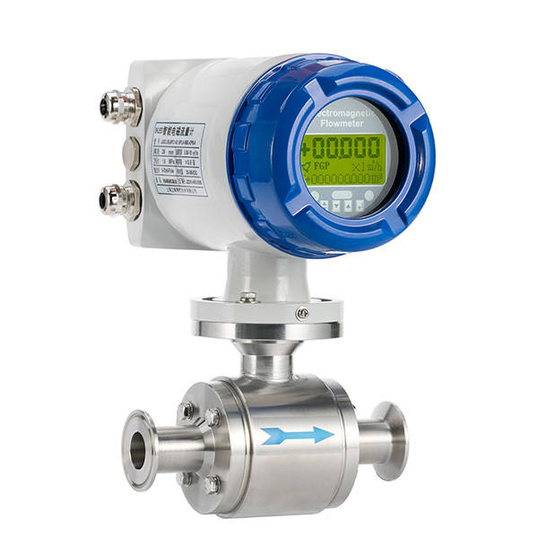
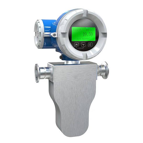
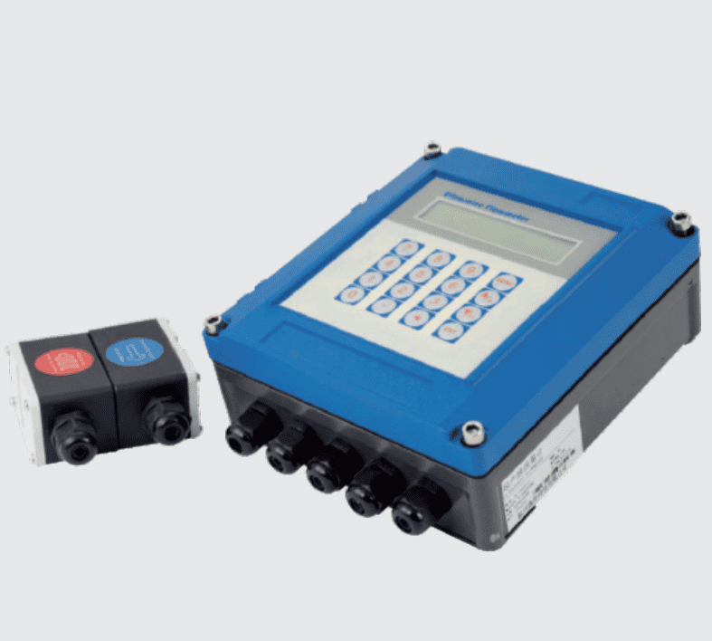
Once you have this dataset, a fast way to cross‑check your options is to browse the manufacturer’s complete Flowmeter series. That page shows side‑by‑side technologies — gear, Coriolis, electromagnetic, ultrasonic — so you can immediately see whether another measurement principle would fit better for a non‑viscous, conductive fluid.
Step 1 — Characterize Your Fluid First, Not the Pipe
What to Do
1. Measure or retrieve the nominal viscosity at the operating temperature. If the fluid starts at 500 cP cold and drops to 50 cP hot, use the worst‑case point for pressure drop calculations. 2. Check chemical compatibility with wetted parts. Circular gear meters from Lisen Measurement commonly offer stainless steel (304/316L) bodies and PEEK, PTFE, or hard‑alloy gears. For food‑grade syrup, specify FDA‑compliant elastomers and approved surface finishes. 3. Identify any solids content. Even soft particles larger than 20 μm can jam the gears. Fit a Y‑strainer or duplex filter upstream — a 40 μm mesh is typical for fuels and light oils, while 100 μm may suffice for heavy crude. 4. Note if the fluid is electrically conductive. If yes and viscosity is low, you might compare against an Electromagnetic flowmeter, but remember a magmeter demands a minimum conductivity (usually >5 µS/cm) and cannot handle hydrocarbons. Gear meters thrive exactly where magmeters stop.
Why This Matters
A circular gear meter is a positive displacement device; it mechanically captures a known volume in each tooth cavity. Changing viscosity does not alter the volume per revolution, so the K‑factor (pulses per liter) stays remarkably stable. That inherent viscosity insensitivity — typically keeping K‑factor variation within ±0.2 % across a 100:1 viscosity change — is the single greatest advantage over turbine or vortex meters, where viscosity shifts can introduce errors exceeding 2 %. Defining fluid specifics upfront prevents choosing a meter whose gears gall due to poor lubrication or whose seals swell from incompatible solvents.
Common Mistakes to Avoid
– Ignoring viscosity at lowest temperature: A pump that circulates heavy fuel oil at 40 °C may deliver 5,000 cP on a winter morning. Select the meter based on that cold viscosity, or the pressure drop may exceed the pump’s TDH. – Assuming all stainless steel is equal: 316L wetted parts handle mild acids, but hot concentrated HCl attacks it. The meter body material must be verified against your specific chemical concentration and temperature. – Skipping the strainer: Even a “clean” oil transfer line collects weld spatter or gasket shreds. A single piece of debris can score the metering chamber and permanently shift the K‑factor.
Step 2 — Size the Meter for Real Flow, Not Just Line Size
What to Do
1. Convert your flow range into the same engineering units used in the manufacturer’s datasheet (usually L/min or GPM). 2. Target a meter size where the normal flow falls between 30 % and 70 % of the meter’s maximum rated continuous flow. Short‑term peaks can touch 90 % without harm. 3. Check the pressure drop curve. For continuous operation on high‑viscosity fluid, keep the pressure drop under 1 bar (14.5 psi); for intermittent dosing, up to 5 bar may be acceptable if the pump can manage. 4. Use the table below as a generic sizing reference for circular gear meters. Exact numbers vary by model, so confirm with the manufacturer’s curve.
| Nominal Meter Size (DN) | Typical Flow Range (L/min) | Max Continuous Viscosity @ 0.5 bar ΔP (cP) | Pulse Resolution (pulses/L) |
|---|---|---|---|
| DN10 | 0.6 – 40 | ~2,000 | 2,500 – 10,000 |
| DN15 | 1 – 100 | ~1,500 | 1,000 – 4,000 |
| DN25 | 4 – 250 | ~1,000 | 300 – 1,200 |
| DN40 | 10 – 600 | ~700 | 80 – 400 |
| DN50 | 30 – 800 | ~500 | 40 – 200 |
Typical figures for medium‑viscosity mineral oil; lower viscosity permits higher max ΔP. Always consult the actual model’s pressure‑drop graph.
Why This Matters
Oversizing a gear meter may seem harmless — the process fluid still flows — but the gears turn at such a low speed that bearing lubrication suffers and output pulses become sluggish, degrading low‑flow accuracy. An undersized meter chokes the line, generates excessive noise, and forces the pump to work harder. In a hydrogen fuel polishing system, for instance, an oversized meter might fail to register pilot‑duty bypass flows, making inventory control impossible. Proper sizing ensures the meter stays in its linear, reliable band.
Common Mistakes to Avoid
– Sizing by pipe diameter alone: A DN50 line carrying 20 L/min of resin does not need a DN50 meter. Match the meter’s measuring range to the actual flow, and use concentric reducers — gear meters tolerate significant reduction without creating turbulence errors. – Missing the pressure drop at peak viscosity: Always request the ΔP vs. flow vs. viscosity chart from the manufacturer. Most selection tools will output a worst‑case figure; if it exceeds your available pump head by more than 20 %, upsize.
Step 3 — Define the Accuracy and Output Needs
What to Do
1. Decide if you need standard industrial accuracy (±0.5 % of reading) or precision/laboratory grade (±0.2 %). Circular gear meters routinely deliver both. 2. Check repeatability requirements. For batching applications, repeatability is often more critical than absolute accuracy; a meter with ±0.05 % repeatability can be calibrated to a master meter for higher absolute precision. 3. Choose your output. A pulse output with 2‑wire Hall‑effect or reed switch suits most batching PLCs. If analog integration is required, add a 4‑20 mA loop‑powered transmitter with HART protocol. This allows remote re‑ranging and diagnostics without climbing into the process area. 4. Determine if you need bidirectional flow measurement. Some LW‑series meters can be ordered with dual pick‑offs to discriminate forward from reverse flow, useful in tank loading/unloading skids.
Why This Matters
Accuracy specifications often appear cryptic: “±0.5 % of reading” is very different from “±0.5 % of full scale.” Positive displacement meters are inherently linear, so their uncertainty as a percentage of reading stays flat across the turndown range. This linearity is critical for custody‑transfer or batching jobs. For ultra‑high precision on clean liquids, a Coriolis mass flowmeter may deliver ±0.1 % of reading directly in mass units, but on viscous fluids, the pressure drop penalty can be steep. Gear meters give the best accuracy‑to‑pressure‑drop ratio for hydrocarbons and polymers.
Common Mistakes to Avoid
– Confusing repeatability with accuracy: A meter that repeats beautifully may still read high or low if the wrong K‑factor is used. Commissioning must include a field calibration master check, especially on large pipe sizes where installation effects exist. – Neglecting pulse resolution: A gear meter with only 20 pulses per liter cannot resolve small incremental doses. For a 50 mL dispense into a cosmetic jar, you need ≥1,000 pulses per liter. Match pulse rate to your batch controller’s minimum pulse width.
Step 4 — Plan Mechanical Installation and Filtration
What to Do
1. Mount the meter in a horizontal or vertical pipe, ensuring the internal gear axis stays level (horizontal shafts) unless the model is specifically rated for vertical axis operation. Vertical mounting can cause uneven bearing wear. 2. Install a bypass loop with isolation valves. This lets you remove the meter for cleaning without shutting down the entire process — a huge productivity win in continuous chemical plants. 3. Place a strainer with differential pressure indication 10–15 pipe diameters upstream. When the ΔP across the strainer rises 0.3–0.5 bar above clean condition, it is time to clean the element. 4. Avoid air entrapment. If the fluid is prone to bubbles, install an air eliminator ahead of the meter. Gas pockets cause measurement errors because the gear cavity then meters compressible volume rather than liquid. 5. Secure the meter without pipe‑stressing the housing. Use flexible connections or support piping independently. Even a small flange torque can distort the chamber and change the clearance gap, shift the K‑factor by 0.3 %.
Why This Matters
A gear meter’s moving parts rely on a thin fluid film for lubrication and sealing. If the meter is installed dry or upside‑down, startup can chew the gears before fluid arrives. Good installation practice extends service life beyond 10 years. Furthermore, because circular gear meters require no straight runs — a major advantage over turbine or ultrasonic meters — space‑constrained skid builders save significant piping real estate.
Common Mistakes to Avoid
– Omitting the bypass: Plant operators forced to stop an entire loop for a meter cleaning will eventually bypass the meter permanently, defeating the measurement. – Skipping an air eliminator in thermally unstable fluids: Hot asphalt or melted wax can release dissolved air, causing vapor lock. A simple float‑type vent solves this. – Hard‑piping without flexibility: Differential thermal expansion between the stainless meter body and carbon‑steel pipe can exert thousands of pounds of force on the meter threads or flanges.
Step 5 — Verify Certifications and Manufacturer Support
What to Do
1. Confirm country‑specific approvals. For the EU, ATEX 2014/34/EU (Ex ia, Ex d) is commonly required. For North America, Class I Div 1 or Div 2 under NEC. Lisen Measurement provides internationally recognized certification for its meter families so that one model can serve plants on multiple continents. 2. Request material certificates per EN 10204 Type 3.1 or 3.2 for pressure‑retaining parts. In the oil & gas and chemical sectors, these are often non‑negotiable. 3. Check if the ISO 9001:2015 quality system is valid and if calibration is traceable to national standards (e.g., CNAS). A valid calibration certificate with actual K‑factor data over five flow points gives you the data you need for the system uncertainty budget. 4. Evaluate post‑delivery support. Shanghai Lisen Measurement & Control Technology Co., Ltd., headquartered at 5F, Building A2, 688 Huancheng North Road, Fengxian District, Shanghai, has a nationwide service network that covers on‑site commissioning and troubleshooting. That geographic coverage matters when a meter is installed in a remote lithium battery plant or a photovoltaic panel coating line.
Why This Matters
A flowmeter is not a commodity fitting; it is a measuring instrument that may require periodic recalibration. A manufacturer that cannot provide re‑calibration services forces you to depend on third‑party labs that may not have the original gear set data. Long‑term partnerships with a supplier like Lisen Measurement — whose team has worked with natural gas, hydrogen, petroleum, and food‑grade processes since 2004 — streamline the compliance paperwork that can delay project handover.
Common Mistakes to Avoid
– Accepting a “generic” calibration sheet: Demand a meter‑specific calibration report with the serial number embedded. It should list K‑factor at minimum, mid, and maximum flow and state the calibration fluid. – Ignoring local hazardous‑area cable gland requirements: Explosion‑proof certification is void if you use unapproved cable entries. Budget for certified glands to complete the Ex installation.
Pro Tips for Success
– Run a viscosity‑loop in your control logic: If your fluid viscosity changes seasonally, program the PLC to apply a small correction factor based on temperature (using an exponential viscosity‑temperature curve). Modern meters with embedded temperature sensors enable digital compensation directly in the transducer. – Combine the gear meter with a batch controller from the same manufacturer: Lisen Measurement’s comprehensive Flowmeter series includes compatible transmitters that can drive valves and totalize batches, cutting integration time. – Use a damping snubber on pulsating piston pumps: Direct coupling of a positive displacement pump with another positive displacement meter creates hydraulic resonance that destroys gears. An air‑filled pulsation dampener placed between pump and meter extends meter life. – Perform an as‑found / as‑left calibration comparison during each shutdown: Documenting the drift over time (typically <0.1 % per year) proves you remain inside your measurement uncertainty window without additional capital.
Frequently Asked Questions
How does a circular gear meter differ from an oval gear meter?
Circular gear meters use two identical round gears with meshing teeth, while oval gear meters rely on two oval‑shaped rotors. The circular design generates less pressure pulsation and often permits higher RPM, but both share the same positive displacement principle. The choice often depends on the manufacturer’s material selection and pressure rating.
Can a circular gear flowmeter measure water?
It can, but it is rarely the best choice. Water lubricates poorly compared to oil, accelerating gear wear. If water is clean and continuous operation is short, a gear meter works; for permanent water service, an Electromagnetic flowmeter typically lasts longer with less maintenance.
What maximum solid particle size can pass through?
A general rule is to keep particles under 20 μm, and in practice, an upstream strainer of 40–100 mesh (about 425–150 μm) protects the meter. Without strainers, even small grit can scratch the hardened gears, increasing internal leakage and reducing accuracy.
Do I need straight pipe runs before the meter?
No. Circular gear meters are immune to velocity profile distortions, so zero straight pipe length is required upstream or downstream. This makes them especially attractive for skid‑mounted systems where space is limited.
How often must a gear flowmeter be recalibrated?
Most refineries and chemical plants recalibrate every 12 to 24 months, depending on fluid abrasiveness and plant measurement audit requirements. Meters on clean, lubricating oil with fine filtration often maintain factory K‑factor within ±0.15 % for over five years.
Conclusion
Choosing The Right Circular gear flowmeter boils down to a disciplined sequence rather than a single spec‑sheet glance: define the real‑world fluid behavior, select a meter size that matches the flow range — not the pipe, align accuracy‑output needs with your control system, install with proper filtration and bypass, and lock in the necessary certifications early. When the steps above are followed, a circular gear meter becomes a reliable workhorse for viscous, clean to moderately fouled liquids, delivering repeatability numbers that few other volumetric devices can match on fuels, polymers, and specialty chemicals. If you are still weighing whether a gear meter or a different technology fits your exact liquid, reach out to the team at Shanghai Lisen Measurement & Control Technology Co., Ltd., who can walk you through a live process evaluation and provide a calibrated solution from their broad Flowmeter series. Start by preparing your fluid datasheet — then let their application engineers handle the sizing math.