Choosing The Right Circular gear flowmeter
You’ve got a fluid to measure. Maybe it’s hydraulic oil feeding a test rig, a precise additive dose in a chemical batch, or the fuel consumption data your customer demands with 0.5% accuracy. The pump is ready, the piping’s in place, and the data logger is waiting. Then the question hits: which circular gear flowmeter do you actually bolt into the line? Not which brand first — which design, which material, which specs match the fluid without ruining the meter or the measurement.
Gear flowmeters have been around for decades, but the variety in bearing materials, seal types, pulse outputs, and pressure ratings can make a shortlist spiral into a dozen datasheets. Selecting the wrong one can mean cavitation damage, a sensor that drifts after three months of abrasive slurry, or electronics that can’t talk to your Modbus network. I’m writing this from years of specifying flowmeters for everything from low-viscosity solvents to viscous polymer melts across industries like petrochemical refining, hydrogen production, and lithium battery manufacturing. Shanghai Lisen Measurement & Control Technology Co., Ltd., founded in 2004 and known through the SHLEES brand, builds circular gear flowmeters that appear in exactly these environments — and we’ll use their LW series as a practical reference point, while sticking to engineering fundamentals any buyer can apply.
By the end, you’ll have a clear method for evaluating gear meters, from fluid compatibility to output signals, backed by real numbers and industry standards. No magic bullet, just a systematic way to narrow the field.
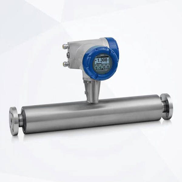
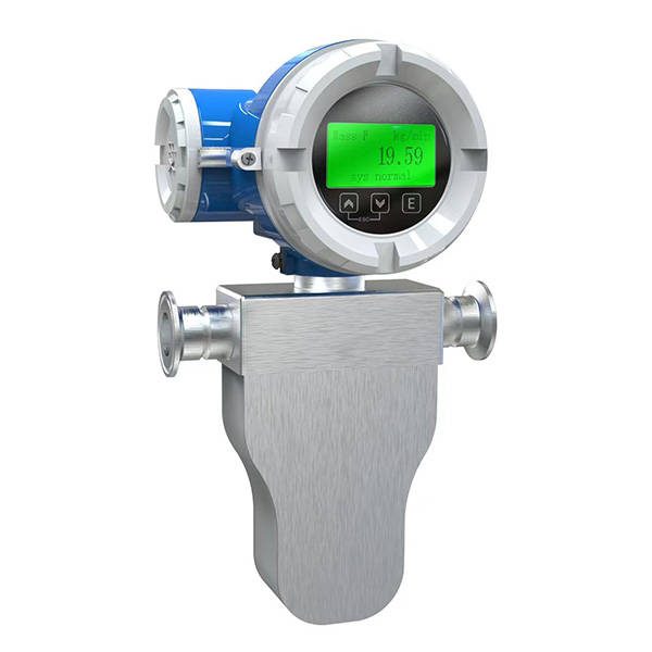
Before we dissect the criteria, it helps to anchor our discussion with the company’s broader portfolio. Their Flowmeter series includes more than just gear meters — it offers context for where the LW circular gear flowmeter fits alongside alternatives. If your application later reveals that a gear meter isn’t ideal, you might consider a Coriolis mass flowmeter for direct mass measurement, or an Electromagnetic flowmeter for conductive fluids. But let’s assume a positive displacement gear meter is on the table. The first job: define what’s flowing.
Viscosity and the Real Limits of Gear Flowmeters
Circular gear flowmeters are positive displacement (PD) devices — two meshed, rotating gears trap a fixed volume between the gear teeth and the housing wall, discharging it with each revolution. That fixed volume, typically called displacement per revolution (cc/rev), is what gives these meters their high accuracy, often ±0.5% of reading or better for the LW series when measuring clean, lubricating fluids. But that accuracy depends heavily on viscosity.
Industry data shows PD gear meters work best when dynamic viscosity is above about 10 mPa·s (cP). Below that, internal leakage — fluid slipping past the gear tips rather than being pushed around — grows fast. In a fluid with only 2 cP (like diesel fuel), a gear meter might still work, but you could see accuracy degrade to ±1% or worse unless clearances are extremely tight, which raises the risk of seizing with the tiniest particle. For hydraulic oils at 30–100 cP, gear meters are in their sweet spot. At 1,000 cP and above (heavy fuel oils, polymers), the meter will still register flow, but pressure drop across the meter can climb sharply. A general rule from positive displacement theory: pressure loss is proportional to viscosity and flow rate. Pushing a 5,000 cP fluid through a meter at 40 L/min could generate a ΔP of several bar, enough to shear certain polymer chains or exceed the meter’s bearing limit.
So step one: obtain the viscosity at the operating temperature, not just a nominal datasheet value. If your oil is 68 cSt at 40°C but your process runs at 80°C, the actual viscosity might drop to 15 cSt. That could push you below the meter’s recommended minimum. Always check the viscosity index and plot the curve.
Material Compatibility That Keeps the Meter Alive
The LW circular gear flowmeter from SHLEES typically features a stainless steel housing and gears, often 316L or a similar grade, with bearing choices that include tungsten carbide or ceramic. This matters because a meter is more than a measurement tool — it’s a wetted pressure boundary. A chemical compatibility chart won’t save you if you overlook the tiny O-ring sealing the sensor probe or the mechanical seal material on a thrust bearing.
For general industrial oils, stainless/316L with PEEK or PTFE bearings and FKM (Viton) seals is standard and works for thousands of installations. For more aggressive media — say, a chlorinated solvent or a liquid with traces of hydrogen sulfide — you might need Hastelloy internals and Kalrez seals. Don’t guess. Send the fluid’s SDS and a full composition breakdown to the manufacturer’s engineering team. Shanghai Lisen’s application engineers, reachable through their contact channels, routinely evaluate these details. Their experience spans lithium battery electrolyte fluids and hydrogen-related processes, so uncommon chemistries aren’t foreign to them.
One often missed detail: if your fluid contains abrasive solids, a gear meter is rarely the right choice. Even tungsten carbide bearings wear over time when a fluid carries silica or catalyst fines. A typical allowable particle size for an LW meter with hardened internals might be under 10 microns, but you must confirm with the factory. No standard covers this precisely, so request documentation from the manufacturer about maximum particle size and hardness based on their own internal testing. A data-driven buyer will ask for a bearing life estimate at a given flow rate and particle load.
Flow Range and the Danger of Oversizing
A circular gear meter always has a minimum and maximum linear flow range, often expressed as L/min. Operating below the minimum means the gears won’t fully seal — leakage overwhelms metering, and accuracy tanks. Operating above the maximum overloads the bearings and can cause cavitation if inlet pressure isn’t sufficient. For the LW series, typical flow ranges might span from 0.05 L/min at the low end for miniature meters up to 250 L/min or more for larger line sizes, but you need to match the model code precisely.
Here’s a quantified, measured principle: a gear meter’s accuracy curve is most linear between 20% and 80% of its maximum rated flow. If your normal operation is 15 L/min, don’t pick a meter with a max of 200 L/min “just in case.” Pick one with a max around 60 L/min so that 15 L/min sits near 25% of span. That keeps the gears rotating fast enough to maintain the fluid film on bearings and seals, which directly prevents dry starts and wear. If your process has extreme turndown — say 1 L/min during startup and 40 L/min during production — a single mechanical gear meter will struggle. In that case, a dual-range setup or a different technology might be needed.
Pressure rating is the next spec. The LW series is often rated for PN40 or PN63 (40 bar or 63 bar) in standard configurations, but confirm the exact figure with the manufacturer. On a hydrogen dispenser loop at 350 bar, a standard gear meter will fail catastrophically. High-pressure versions exist but aren’t a given. The rule is simple: the meter’s rated pressure must exceed your system’s maximum operating pressure during surge or dead-head conditions, not just normal running pressure. A hydraulic test stand with a relief valve set at 210 bar needs a meter rated for at least 250 bar, possibly with a safety factor of 1.5 per ISO 5167 guidelines for pressure devices.
Electrical Outputs That Talk to Your System
Mechanical registers are almost obsolete in new installations. Today’s gear flowmeter buyers need to match the output signal to their PLC, data logger, or process controller. The LW series can be equipped with a range of pickups: typically a Reed switch (dry contact), a NAMUR proximity sensor (for hazardous areas), or a Hall effect sensor providing a square wave pulse. The pulse frequency correlates with flow rate, giving a K-factor in pulses per litre that is constant across the linear range. A meter might output 1,000 pulses/L, meaning at a flow of 10 L/min you’d see about 167 Hz. That’s well within the capability of a standard PLC counter card.
More advanced meters may offer a 4–20 mA analog output via an integrated transmitter, or a digital protocol like Modbus RTU. If your control system uses Modbus RS-485, ask whether the meter electronics supply a register map with totalised volume, flow rate, and diagnostic flags. This avoids the need for an external signal converter and simplifies wiring. For battery manufacturing facilities where SHLEES products are deployed, Modbus communication is often the preferred backbone, so specifying the right output from the start saves integration time.
Always verify the power supply requirements: a Hall sensor typically needs 5–24 VDC, a 4–20 mA loop requires a suitable supply voltage to drive the loop resistance. And if your site is in Zone 1 or Zone 2 hazardous area, the sensor must carry an ATEX or IECEx certification. NAMUR sensors are designed for this and work with isolating switch amplifiers.
Sizing and Installation That Prevent Measurement Drift
A gear flowmeter is sensitive to flow disturbances, but unlike a turbine meter, it’s not sensitive to swirl. You don’t need long straight runs upstream. However, you do need to eliminate air or vapour entrainment. A positive displacement meter measures total volumetric flow — if 5% of the volume is air bubbles, the reading will be 5% high. A small air release valve or a back-pressure valve downstream can keep the fluid in a fully liquid state. For volatile fluids, maintain at least 1–2 bar back-pressure above the fluid’s vapour pressure at operating temperature to prevent cavitation.
Mounting orientation matters. The LW meters are typically designed for horizontal mounting with the gears in a vertical plane, but check the installation manual. If mounted vertically, internal drainage after shutdown could lead to dry starts. A dry gear set spinning at 1,500 RPM without lubrication can gall in seconds. Some meters incorporate a bypass or a startup procedure to pre-fill the chamber.
Filtration is non-negotiable. Because gear clearances are measured in microns, a strainer or filter upstream is required. A standard recommendation is a mesh size one step finer than the minimum clearance — if the meter’s smallest gap is 20 microns, install a 10-micron filter. A dirty filter increases pressure drop, so add a differential pressure gauge or switch. A sudden rise in ΔP across the filter often precedes meter damage.
Here’s a table summarising the key selection criteria we’ve covered, mapped to typical parameter ranges:
| Selection Factor | Typical Range / Requirement | Notes |
|---|---|---|
| Fluid viscosity | 10–1000 mPa·s (optimal) | Below 10 cP, leakage errors rise; above 1000 cP, pressure drop increases |
| Operating pressure | Up to PN63 (63 bar) standard meters | High-pressure versions to 400+ bar available on request |
| Flow range accuracy band | 20–80% of maximum rated flow | Linear K-factor within this band, typically ±0.5% of reading |
| Material choices | 316L housing, carbide/ceramic bearings, FKM or Kalrez seals | Match to fluid SDS |
| Output signal | Pulse (Reed/NAMUR/Hall), 4–20 mA, Modbus RS-485 | For PLC integration, pulse is simplest; Modbus adds diagnostics |
| Filtration requirement | 10–20 micron absolute | Required upstream; finer than smallest internal clearance |
| Installation | Horizontal preferred, minimal straight run | Provide back-pressure to suppress cavitation |
Avoiding the Trap of Price Alone
Procurement departments love to bid three suppliers and pick the lowest price. With precision flowmeters, that’s a trap. A gear flowmeter’s life-cycle cost includes calibration, spare parts, and downtime. Two meters with the same datasheet accuracy of ±0.5% can perform very differently after 6,000 running hours if one uses plain carbon steel bearings and the other uses tungsten carbide. The first will show accuracy drift as clearances widen; the second will hold its calibration longer. Internal data from bearing manufacturers, such as those supplying to positive displacement meter builders, shows that a carbide bearing can have a wear rate 5–10 times lower than hardened steel under the same lubricated conditions. Ask for a bearing material specification and a mean-time-between-overhaul estimate. A reputable manufacturer like Shanghai Lisen, with its nationwide service network and engineering support, can provide these numbers rooted in field data from industries like natural gas, hydrogen, and food processing.
Beyond the initial purchase, factor in calibration. Inline calibration without removing the meter is ideal — some meters accommodate a master meter connection. At a minimum, plan to send the meter for bench calibration every 12–24 months, depending on fluid corrosiveness. The cost of recalibration often equals 20–30% of the meter price over a 5-year period, but it’s a fraction of the cost of a bad batch or a production shut-down due to inaccurate dosing. Standards like ISO 2714 for liquid hydrocarbon measurement or OIML R117 for dynamic measuring systems can guide calibration intervals, but the meter manufacturer’s own testing data is your best benchmark.
Common Pitfalls and How to Sidestep Them
One frequent misstep is specifying a gear meter for a fluid that undergoes phase change. If your liquid can gel or crystallise at ambient temperature, a meter full of solidified fluid will destroy itself on startup. Heat-tracing and insulation may solve it, but not always. For high-melt-point waxes or bitumen, consult the manufacturer before ordering.
Another error is ignoring pressure spikes. Water hammer — sudden closure of a downstream valve — can generate pressure surges several times the system pressure. If the meter sees a transient peak of 400 bar on a PN63 meter, the gears may fracture. A simple relief valve upstream, sized for the meter’s maximum pressure, is cheap insurance.
Don’t forget that gear flowmeters are volumetric meters. They measure actual volume at line conditions, not standard volume or mass. If your process requires mass (kg/h), you must compensate for density. This means adding a temperature sensor and a density calculation, or integrating with a flow computer. The meter’s pulse output can feed a density-compensated totaliser, and Shanghai Lisen’s range of instruments includes pressure and temperature transmitters that can complete the loop.
Finally, confirm that the meter can be opened for cleaning without special tools. In food or coating applications, a CIP (clean-in-place) capable design might be necessary; sanitary models with EHEDG certification exist, but the standard industrial LW series might not meet that. Verify the surface finish (Ra) specification if product purity matters.
Questions That Come Up Before Every Purchase
Can I use a circular gear flowmeter with water?
Yes, if the water is clean, non-corrosive, and contains enough lubricity — but water has a very low viscosity (1 cP at 20°C). Most gear meters will see significant internal leakage, and accuracy may degrade to ±2% or worse unless the meter is specifically designed with ultra-tight clearances. For water, an Electromagnetic flowmeter is often a better choice.
How do I know when the bearings are wearing out?
Watch the K-factor over time. If your meter’s original K-factor was 1000 pulses/L and a year later it becomes 980 pulses/L, the displaced volume per revolution has changed — likely due to clearance wear. Regular calibration checks reveal this trend. Many users log the K-factor monthly and set an alert if it shifts by more than 1%.
What’s the maximum particle size allowed in the fluid?
It varies by design, but as a general guide, particles should be no larger than one-third the smallest internal clearance. If the gap is 20 microns, filter to 10 microns absolute. Always request the manufacturer’s specific recommendation based on their bearing and gear profile.
Does the meter require a specific orientation for vertical lines?
Flow direction can be vertical, but mounting the meter horizontally with the gears on a vertical axis is typical. Vertical upward flow can work, but downward flow may leave the chamber partially filled. Check the installation manual for your specific LW model code. Adding a non-return valve can prevent backward flow during shutdown.
Can I use the same meter for multiple fluids?
Only if the fluids are chemically compatible with the wetted parts and have similar viscosity ranges. Cross-contamination and cleaning residues are real concerns in batch processing. A dedicated meter per fluid or a thorough flushing procedure is safer. An Coriolis mass flowmeter can handle multipurpose lines because it measures mass directly and has fewer crevices, but it’s a different investment.
A Methodical Close
Choosing the right circular gear flowmeter starts with your fluid’s viscosity at the actual operating temperature, followed by a hard look at materials, pressure, and the flow range you genuinely need. Not the maximum your pipe can carry, but the range where your process spends 90% of its time. The LW circular gear flowmeter from SHLEES, built by a manufacturer with two decades of instrument engineering, offers a stainless steel platform with bearing and seal options that cover many industrial oils, solvents, and process fluids. You have a direct line to application engineers via the company’s Shanghai headquarters — use that. Send them the fluid data, the flow profile, and the electrical requirements. A measured conversation rooted in engineering facts will always outperform a generic datasheet comparison.
Where you go next depends on your timeline. Request a test to validate the K-factor with your own fluid at a flow lab, or ask for a factory calibration certificate traceable to national standards. If the application is borderline — very low viscosity, high abrasion, extreme temperature — then stepping back to compare the gear meter with alternative technologies in the broader Flowmeter series is a prudent second step. Matching the meter to the fluid isn’t complicated once you apply the filter of viscosity, material, signal, and installation rules. The real work is getting the right data before you sign the order.